There are innumerable designs possible using biamp devices, emitters and other compatible devices. The sections that follow gives basic instructions on the steps required to design a sound masking system using Qt X software. This section is intended as a guide to familiarize a user with the tools and elements of Qt X and the steps required to successfully design and deploy a sound masking system. There are many considerations with regard to design and deployment of a successful sound masking system. Additional articles about Qt X systems (design, configuration, programming, etc) are available on Cornerstone here.
Sound masking systems may be installed in almost any size space. The variety of Qt X sound masking controllers available and the flexibility locations (rack, wall & plenum) provide sound masking designers with many different options. The most common spaces to utilize sound masking are:
Successful sound masking requires a different approach than 'normal' audio infrastructure in order to achieve optimal results. Sound masking must be properly calibrated to achieve a consistent and favorable experience for building occupants. Sound Masking 'Zones' must be determined when designing a layout - how these zones are designed and configured will vary greatly depending on factors such as the type of space, ceiling height, the need for additional audio sources/paging, etc.
Sound masking device types may be intermixed within a greater sound masking system as needed based on design considerations. Examples of various layouts are provided, yet innumerable design possibilities exist. Units come pre-configured out of the box to simplify initial set-up.
The basic workflow for creating a sound masking system is as follows:
Mount & install cable and components
Power & test emitters/speakers
Adjust zone on front panel to a low but audible level
Walk emitter/loudspeaker locations to verify sound masking signal is present at each location
Install and connect peripherals (paging, audio sources, life safety panel, etc.)
Verify proper operation of each source and contact closures
Discover controllers and other devices connected to the network via Qt X web UI or Qt X software
Configure controllers IP Address, Network Operation Mode (single/dual network cable)
Add controllers (by serial number) to proper location via Qt X web UI or Qt X software
Update firmware for all controllers
Create zones as required
Assign controller outputs to zones
Create music and paging Audio Sources and assign to Zones (ensure emitter/loudspeaker type in use supports audio sources)
Discover and configure NPX paging stations if applicable
Define behaviors of input/outputs for all devices
Set zone sound masking levels (42dBASPL to 48dBASPL) using a calibrated sound pressure meter. Measure at a 4ft. (1.2m)
Adjust masking spectrum equalizer for each output as necessary to meet project requirements
Set system security/user levels and document passwords
Assess zone audio - adjust as required
Capture final sound masking spectrum and sound pressure level measurements for reporting if required
If necessary, set soft start, schedules, etc.
Save & backup Configuration using Qt X Software
All Qt X devices except the 800/800D are shipped with an appropriate power supply. The Qt X 800/800D is intended for plenum installations and requires a PoE+ power supply. When installing any devices, emitters and their associated power and network cabling in a plenum space or elsewhere, be sure to follow all regulatory/safety requirements.
The sections that follow are organized by product type, but it is important to note that a single sound masking system may incorporate both the Qt X 300/600/300D/600D and Qt X 800/805/800D/805D sound masking devices and their associated speakers, audio and network devices.
The following sections are specific to the Qt X 300/300D & 600/600D.
Emitters should be connected to the Qt X device with CMP-type plenum rated, UTP four-pair category cable with EIA/TIA 568B standard terminations.
The first cable run that connects the Qt X device to the first emitter (passive emitter installation) or the Qt Active Emitter Power Injector’s signal input (active emitter installation) is referred to as the Home Run cabling for reference purposes throughout this and other Biamp documents referring to sound masking technology. Cables that connect emitters are known as interconnect cables.
The Home Run cable is typically supplied by, cut to length and terminated by the installer.
Interconnect cables connect the output jack of one emitter to the input jack of the next emitter in the run in a daisy chain. In active emitter installations, the interconnect cable carries the DC voltage from the injector as well as the audio signal from the Qt X device, behaving as a powered signal cable. In passive emitter installations the daisy-chained interconnect cables carry four channels of audio directly from the Qt X to the emitters, therefor behaving as a signal cable.
Qt active emitter installations require 14 AWG two-conductor type CMP cabling to deliver DC voltage from the Qt Active Emitter Power Supply to the Qt Active Emitter Power Injector.
As noted in Emitter & Speaker Types, active and passive emitters may be intermixed in a sound masking project on the same Qt X device, as long as all emitters in a particular output/run are the same type. For example, a sound masking system equipped with a Qt X 300 may have passive emitters in an open office zone that supplies sound masking, another zone (private offices for example) that provides sound masking and paging via standard emitters, and a 3rd zone (a reception area) that has active emitters providing sound masking and music. Each of those zones would have a different output assigned to them.
Active emitters may be set to reproduce either a standard or active (lower frequency extension) sound masking spectrum, whereas the passive emitters may only reproduce the standard spectrum. When different emitters are used in different zones, best practice dictates that the standard spectrum type be used in adjacent zones on all emitters. This will closely match the sound signature an occupant hears throughout a building. If active emitters are used throughout a building, either spectrum will provide the same speech privacy experience when adjusted to the same overall sound level.
Technical Note - Emitter wiring (both Passive and Active)
As noted above, the signal cables carry four (4) channels of audio from the controller to the emitters. To prevent emitters from playing the same channel, they are designed to "rotate" the channels so that the next emitter in the sequence is playing a different channel from the current emitter. Each emitter loads the second channel on the cable connected to its input and changes the order of the channels going to the output connector. When emitters are correctly connected the simplified result is shown below for Run A starting with Channel 2. Run B runs from Channel 4 to 1, to 2, to 3, and then repeats.

The table that follows gives information about cabling types and maximum distances based on the emitter installed.
|
Cable |
Cable Type |
Qt Passive Emitter - Max Cable Distance |
Qt Active Emitter- Max Cable Distance |
|
Signal Cable |
|
1000 ft (304.8 m) (from Qt X device to last emitter) |
1000 ft (304.8 m) (from Qt X device to last emitter - includes powered signal cable length) |
|
Powered Signal Cable |
|
N/A |
400 ft (122 m) (from PoE injector output to last emitter) |
|
Power Cable |
|
N/A |
400 ft (122 m) (from power supply to PoE injector) |
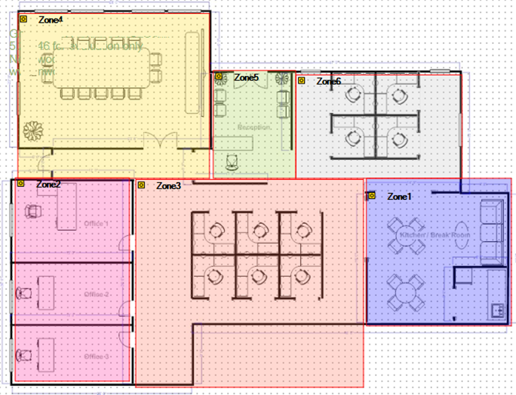
As previously noted, system zones will be designed/configured based on factors such as the type of space, ceiling height and the need for additional audio sources. Additional zones will also be required in situations where ceiling height varies by more than 6 inches (15.24 cm) in a given space. This allows for adjusting audio to compensate for differing ceiling heights while maintaining a consistent sound masking experience. Whenever possible, sound masking zones should begin and end at physical boundaries so sound masking is 'wall to wall'.
Each sound masking zone may have up to two cable runs of UTP category plenum cabling. Each cable contains four non-time correlated sound masking channels to avoid interference of adjacent emitters.
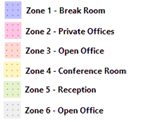
The image below shows how several sound masking zones may be placed in a layout to cover different spaces on the same floor. Note the zone boundaries follow the physical boundaries of the space in most of the layout:
Physical considerations such as ceiling type, height, surfaces (drywall, wood panels) and room size are extremely important when determining the number of emitters to install in an area and their spacing. Sections that follow give details on successful deployment of a sound masking system in different room environments.
Best practice for consistent sound masking is placing emitters in a square/rectangular pattern to provide uniform sound coverage throughout a space. In open office environments where open and partial ceilings exist, optional mounting brackets allow for installing the emitters on structural beams and other surfaces. Emitter spacing is directly proportionate to ceiling height and applies to both active and passive emitters. Minimum/maximum spacing from acoustic barriers such as walls and columns is also the same for both emitter types. If emitters are too close or too far away from a physical boundary there will be a noticeable change in the audio level in that area which creates a unfavorable sound masking experience for building occupants.
In-ceiling conflicts/obstructions (such as light fixtures, sprinklers, etc.) may be present that inhibit equal and optimal spacing of the emitters. Emitters may be moved up to 2 ft (.6 m) to accommodate for such obstructions, but consistency in spacing is optimal.
Detailed specifications and requirements for spacing emitters in open offices and large spaces are in the table below. Note that emitter installations in acoustic ceiling tiles (ACT) will be spaced differently at some ceiling heights based on the dimensions of the ceiling tile.
|
Emitter Mounting Height* |
Emitter Spacing - 2'x2' ACT, Open or Solid-Surface Ceilings |
Emitter Spacing - 2'x4' ACT Ceilings |
Min Distance to Wall/Obstacle |
Max Distance from Wall/Obstacle |
|
< 8' to 9' (2.4 to 2.7 m) |
8' x 8' (2.4 x 2.4 m) |
8' x 8' (2.4 x 2.4 m) |
2' ( .6 m) |
4' (1.2 m) |
|
9' to 10' (2.7 to 3.0 m) |
10' x 10' ( 3.0 x 3.0 m) |
10' x 8' ( 3.0 x 2.4m) |
2' ( .6 m) |
5' (1.5 m) |
|
10' to 11' (3.0 to 3.3 m) |
10' x 10' ( 3.0 x 3.0 m) |
10' x 8' ( 3.0 x 2.4m) |
2' ( .6 m) |
5' (1.5 m) |
|
11' to 12' (3.3 to 3.6 m) |
12' x 12' ( 3.6 x 3.6 m) |
12' x 12' ( 3.6 x 3.6 m) |
2' ( .6 m) |
6' (1.8 m) |
|
12' to 14' (3.6 to 4.2 m) |
12' x 12' ( 3.6 x 3.6 m) |
12' x 12' ( 3.6 x 3.6 m) |
2' ( .6 m) |
6' (1.8 m) |
|
over 14' (4.2 m) |
Contact Biamp Support |
Contact Biamp Support |
2' ( .6 m) |
7' (2.1 m) |
* Mounting height may not always be at the ceiling height
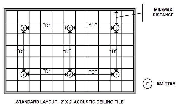
Using the dimension in the table above, the illustration below gives an example of a spacing emitters in an area of an open office with 2' x 2' acoustic ceiling tiles installed throughout. "D" is equal to the dimensions in the 2nd column based on the ceiling height in the first column. Min/Max distances from an obstacle are given in the 4th and 5th columns.
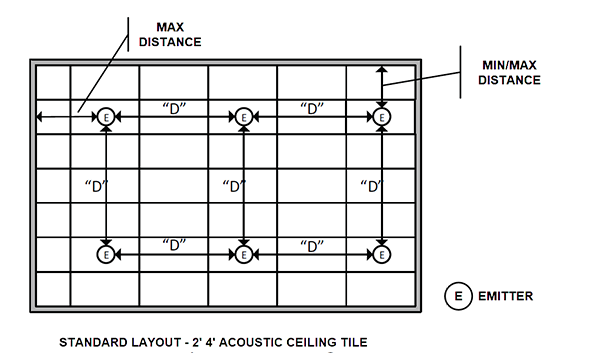
Using the dimension in the table above, the illustration below gives an example of a spacing emitters in an area of an open office with with 2' x 4' ACT installed throughout.
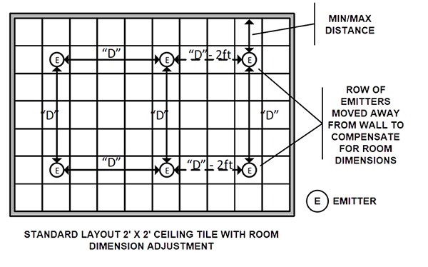
In some instances it will be necessary to decrease the distance between emitters in the last several rows to accommodate for room dimensions. It is best practice to decrease distances rather than increase to maintain adequate coverage.
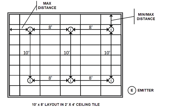
Due to aesthetic concerns, it may required to install emitters in the center of a ceiling tile. In the example below, a 10' x 8' grid is used in 2' x 4' ft. ceiling tiles to accomplish this. This approach may be used in cases where ceiling height would allow for 10' x 10' ft. spacing but the aesthetic impact is objectionable.
Small spaces and enclosed offices typically require at least two emitters per space (i.e. two channels of sound masking) to keep listeners from focusing on the sound from any one emitter. Emitter spacing and layout is shown in the table below.
|
Area |
Emitter Quantity |
Layout |
|
180 sq ft (16.72 m²) |
2 |
|
|
180-260 sq ft (16.72-24.15 m²) |
3 |
|
|
260-340 sq ft (24.15-31.59 m²) |
4 |
|
|
340-420 sq ft (31.59-39 m²) |
5 |
|
|
420 - 500 sq ft (39 - 46.45 m²) |
6 |
|
|
> 500 sq ft (46.45 m²) |
Use large space/open office layout |
|
Some spaces are suited to a single emitter, as long as the space has a limited occupancy time and is, by design, a small space intended for privacy (mothers rooms, exam rooms ,etc.) A single emitter installation should only be installed if the following criteria is met:
Occupancy of the space is usually an hour or less.
Room size is equal to or less than the rooms based on ceiling height in the table that follows.
A dedicated zone is used for a use similar to a single-emitter room, which allows for adequate adjustment.
|
Emitter Mounting Height |
Maximum Room Size |
|
8' - 9' (2.4 - 2.7 m) |
< 64 sq ft (5.9 m²) |
|
9' - 11' (2.7 - 3.3 m) |
<100 sq ft (9.3 m²) |
|
11' to 14' (3.3 - 4.2 m) |
< 144 sq ft (13.4 m²) |
|
over 14' (4.2 m) |
If the small space does not fall into the criteria above, refer back to Enclosed Rooms/Private Offices for design considerations.
Since training and conference rooms are usually used for communicating clearly, they are not typically considered candidates for installing sound masking equipment. If a training/conference room is considered a multipurpose room where sound masking may be required in some situations, certain criteria must be met. Rooms larger that 300 sq ft should not be included in the sound masking plan unless one of the following exceptions apply:
Sound masking may be configured with a 3rd party controller that has the ability to disable sound masking in the room as a separate zone.
An in-room volume controller can reduce/disable masking.
In some cases sound masking could be necessary in conference and training rooms if conversations outside the room are easily overheard due to location, wall construction, etc. Placing the sound masking emitters outside the room (where a listener may overhear the conversations) is always the best practice.
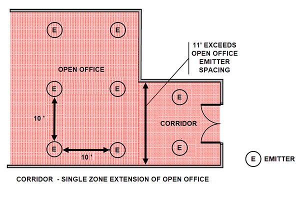
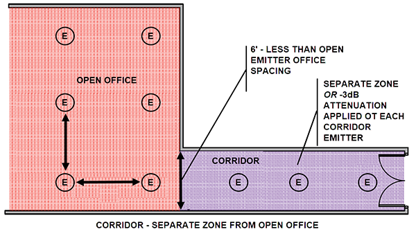
Emitter spacing in a hallway/corridor should usually adhere to the same standards and design considerations given in Large Space/Open Offices. In most scenarios, each hallway/corridor should be treated as a separate sound masking zone to allow independent level adjustment. This is extremely important when adjoining areas of 'lower' sound masking levels (such as private offices).
Exceptions to this may occur in the following scenarios:
When a wide hallway extends from an open office area continuing the open office zone into the hallway is permissible (the hallway width is greater than the emitter spacing in the open area.)
DIP switch attenuation (down -3 dB) may be applied to emitters in an adjacent hall if the hallway is narrower than the emitter spacing in the open area. This will allow for a keeping the hallway and open area in a single zone.
