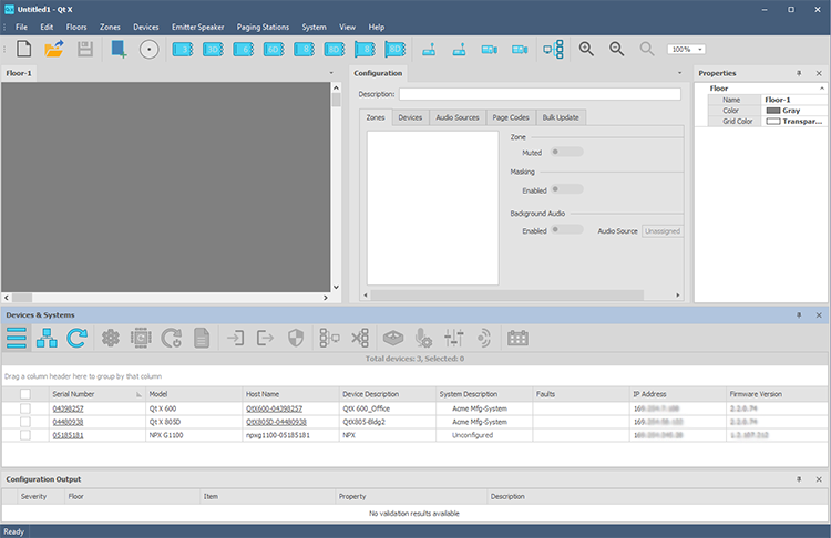
The primary design interface screen allows a users to perform all functions necessary to design, configure and control a sound masking system. The interface allows a user to import representations of floor plans, customize sound masking zones, add Qt X sound masking devices, emitters/speakers, NPX paging stations, other audio source devices, as well as a multitude of other functions.
Click the links to jump to a specific element/topic:
Main Menu Tool Bar Floor Plan Configuration Properties Devices & Systems Configuration Output
The interface consists of multiple elements and tools which are used to design a sound masking system. Qt X has intuitively-formatted tool bars, pods and windows which make importing devices and floor plans and configuring a system simple and intuitive.
The sections below give basic information about these elements. Links within each topic connect to in-depth descriptions of these elements and how a user may manipulate them to achieved desired results.
The Main Menu provides the basic functions of Qt X. Users may open, save and create new files, edit numerous elements of the floor plan image, insert devices, emitters and NPX paging stations, and toggle between various views. Main Menu buttons may be added or removed and further customized. The Main Menu is dockable or may float on the Qt X interface or elsewhere on the user's screen as desired. Click here for more information on the functions of the Main Menu.
The Tool Bar duplicates many functions of the Main Menu, including opening, saving, and creating new files as well as adding Qt X and NPX devices, emitters and new floor plans. Tool Bar buttons may be added, removed or further customized. The Tool Bar is dockable or may float on the Qt X interface or elsewhere on the user's screen as desired. Click here for more information on the functions of the Tool Bar.
Users may choose to import an image that represents the actual space in which the sound masking system is being installed, but it is not required. Floor plan images may be imported as a .pdf or numerous raster formats (.bmp, .jpeg, .png, etc.). Multiple floors may be added to the floor plan screen and toggled by clicking the desired tab at the top of the screen. Click here for more information on floor plans.
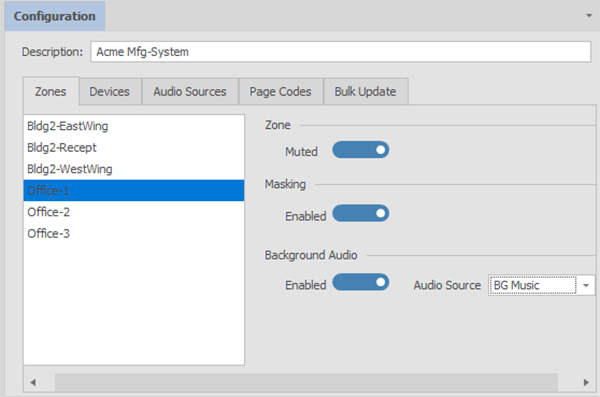
The Configuration window gives information and allows for the configuration and customizing of zones, devices, audio sources and page codes. A bulk update of like devices is also available from this window. See Configuration for details.

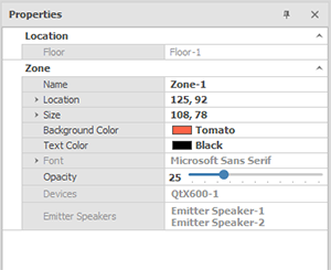
When devices, emitters, etc. are added to a design, the Properties window will give information about, and allow editing of the device, floor plan, etc. The Properties window is dockable. Elements are determined by the type of device (QtX controller, NPX paging system, etc) and may be edited from the Properties window. Non-editable fields are in light grey text.
Different properties will be available depending on the element selected. The image below shows options when a Zone is selected.

When a different element of the layout is selected, the Properties tab will reflect that selection, and allow editing of appropriate elements.
The Devices & Systems is a dockable window that shows discovered devices on the network as well as systems that have been created. Users may toggle between viewing devices and systems by clicking the icons as shown:
 |
Devices |
 |
System |
Click here for more information on managing devices.
Click here for more information managing systems.
The Configuration Output window will list information and errors encountered during the system configuration. It does not monitor the system or devices in real time.
The Configuration Output window will provide a list of any errors and information:

Error icons in the output window indicate why the system did not configure. Any Errors present will not allow a system to configure, but Info concerns do not necessarily prohibit configuration (unless an Error accompanies the Info indication). In the example above the configuration failed due to the errors listed.
A configuration did not send if errors ![]() are present (shown in the Severity field.) A description is given that will assist the user in determining problems with the system design.
are present (shown in the Severity field.) A description is given that will assist the user in determining problems with the system design.
Info ![]() will not impede sending a configuration but the system will not work as designed if devices are not assigned to a physical device or if assigned devices are part of another system, etc.
will not impede sending a configuration but the system will not work as designed if devices are not assigned to a physical device or if assigned devices are part of another system, etc.
In the example below, a device in the layout was not assigned to a physical device as indicated by the Info field, yet because other devices were assigned appropriately, the system was allowed to configure with the physical devices present:

Errors may be corrected and the configuration re-sent as needed to properly configure the system.