
The Main Menu provides the basic functions of Qt X software. Users may open, save and create new files, edit numerous elements of the floor plan image, insert devices and emitters, and toggle between various views. Main Menu buttons may be added or removed and further customized. The Main Menu is dockable or may float on the Qt X interface or elsewhere on the user's screen as desired.
Note that numerous functions available from the Main Menu are also available from the Tool Bar.
The images below show the Main Menu docked and floating:
Buttons may be added/removed by clicking the arrow in the right corner of the menu:
Follow the links below to jump to a menu item:
File Edit Floors Zones Devices Emitters & Speakers Paging Stations System View Help
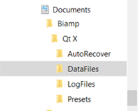
The default file save location is in the user's Documents Biamp QtX DataFiles folder.
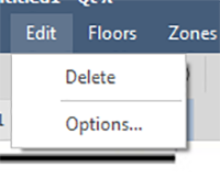
The Delete portion of the Edit tab menu allows users to delete a selected item in the layout. The Options button allows users to toggle between Normal and Dark Mode, use large toolbar buttons, or bypass HTTPS authentication. Click OK to set the options.
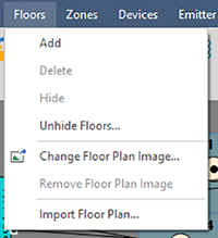
The Floors tab allows users to make numerous changes and additions to the floor plan images in the design layout. When adding or changing a floor plan image, users will need to browse and select a supported file (.BMP, .JPG, .PNG .PDF) when prompted.
|
Menu Item |
Function |
|
Add |
Adds a floor to the current design; users may update the properties including the name, and import an image (Import Floor Plan). |
|
Delete |
Deletes the selected floor. |
|
Hide |
Hides the selected floor. |
|
Unhide Floor |
If one or more floors are hidden, allows a user to select which to make visible in the design interface. |
|
Change Floor Plan Image |
Allows user to change the floor plan image. |
|
Remove Floor Plan Image |
Allows user to remove the floor plan image. |
|
Import Floor Plan |
Adds a new floor and imports the floor plan image with one action. |
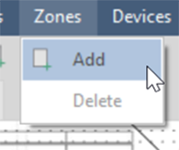
The Zones tab allows users to create sound masking zones over a floor plan layout. Users can determine how many separate zones will be required based on design considerations of the floor space.
Clicking Add Zone will enable a user to place a zone on the floor plan. Determine the approximate location for the zone and click to place it:
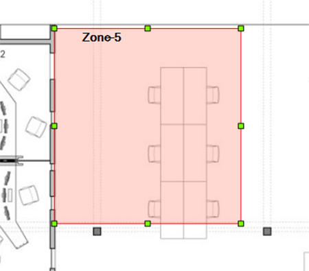
Note that the software allows placing multiple zones sequentially - click ESC once all zones have been placed on the layout.
Once placed, use grips to adjust the size of the zone:
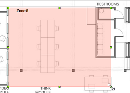
When selected, the Zone size, color, transparency, etc. may be edited in the Properties window.
Once a zone is placed on the design layout, users may configure audio parameters from the Zones tab in the Configuration.
Users select and place Qt X devices from the Devices drop-down. A selected device can also be deleted from the layout by pressing the Delete option.
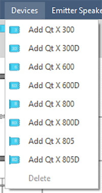
Choosing which device to use will vary depending on the number of zones in a sound masking system, whether the system audio is processed via Dante® or AVB and where, physically, the device is to be located. Click the links below for detailed information about each of the available devices:
Device logic settings are available from the Configuration window.
NOTE: Regardless of the physical device installed, the same method and icon is used to place an emitter or speaker. Differentiation is made based on the Qt X device connected and will be reflected in the Outputs field of the Configuration window.
Add and delete emitters & speakers from this menu item:
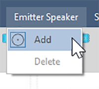
Place emitters on the floor plan as required:
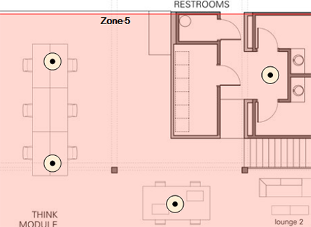
Users may continue placing emitters without having to go back to the menu drop down. Click ESC to stop placing emitters/speakers.
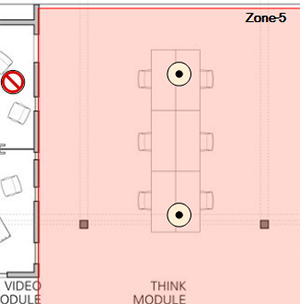
The software will not allow placing emitters or speakers outside a Zone:
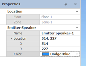
When an emitter is selected, certain values are shown and may be edited from the Properties window, such as the name, location and color. Location fields (zone and floor) are not editable. The emitter may be moved by changing the X,Y axis or by dragging it to a new location.
To connect emitters and speakers to a device and the other emitters or speakers in the layout, click the node in the device or emitter. Connections will snap to the closest emitter or speaker in the direction the pointer is moved after clicking the node as shown in the clip below:
NOTE: There is no requirement to place an emitter/speaker icon in the layout to represent every emitter or speaker that is physically present. Although the designer may choose to do so to create an accurate representation of the physical installation, only one emitter/speaker per output to represent a run is necessary.
IMPORTANT: When creating a layout, best practice is to place a zone (or zones) on a floor first, then add devices and emitters. Emitters can only be placed in a zone, and Qt X devices must be outside of the zone in order to make connections to the emitters.
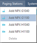
NPX paging stations can be added to the floor layout. Use the menu dropdown to select a model then click on the floor layout (not in a zone). The corresponding icon will appear (grey) on the layout and a name box will pop up. Fill in the name and click OK.
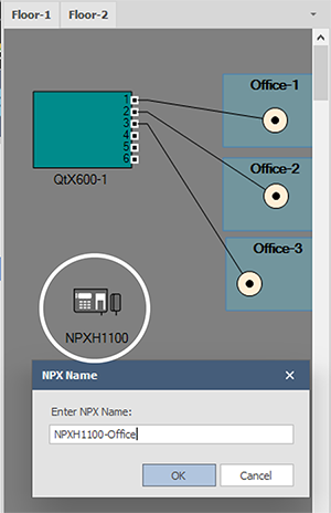
The NPX icon must be assigned to a discovered NPX device and then associated with a Qt X controller (Proxy). Select the NPX icon - a box will appear around the NPX device icon. In the Assignment section in the properties box, chose the Physical Device from the drop down of discovered NPX devices. Once it is associated with a physical device, the icon will turn blue.
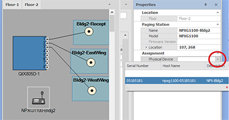
To associate a NPX device with a controller, click on the NPX device, open the Proxy dropdown menu, and choose a controller on the same floor layout. This associates the NPX device with a controller - see NPX device quantity limitations in the Important note below. Both assignment fields must be filled for the device to become part of the system. Save the changes.
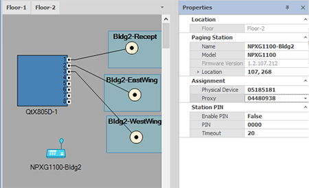
IMPORTANT: The Qt X software v2.2 release will reliably support up to 16 NPX devices in a single system. A maximum of 4 NPX stations may be associated with a single Qt X controller (Proxy). Support for more than 16 NPX stations per system will be available in a future release.
The Send Configuration option in the System drop-down is used to send a configuration to a system. This can also be accomplished by pressing the same icon on the top tool bar
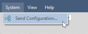
Once a layout is designed, the user may configure the physical devices and zones. Click here for detailed information on configuration.
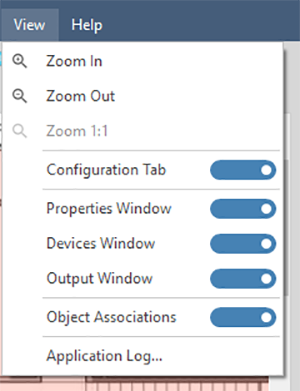
The View tab allows users to hide/show particular functional windows. Users may also zoom in and out on the layout from this drop-down as well as view or save application logs.
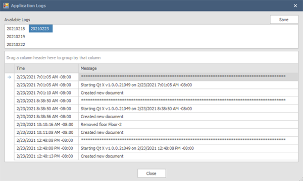
Selecting the Application Logs option allows users to view application changes and details. These are selectable by date. Logs may be saved to a location as a .log file.
The help menu has a link to this help file as well as the "About" screen noting the version.