The properties box is a docking window in the Qt X interface that displays and allows editing of properties for floors, zones, emitters & speakers, devices and audio sources.
Properties described as 'not user-editable' indicate that the field may not be changed. Changes in the layout will be reflected in the Properties content.
The content will update automatically based what is selected in the layout (i.e. if an emitter is selected, the emitter properties will be shown; if a user selects the Zone, the zone properties will be shown, etc.). Elements for these properties boxes are noted below.
Click the link to jump to a specific element:
Floor Zone Emitter & Speaker Device Connector
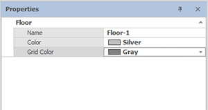
The Floor properties only allows changing the selected floor plan name, color and grid. the grid is transparent by default.

|
Field |
Properties |
|
Name |
User editable |
|
Color |
Sets the color of the floor overlay |
|
Grid Color |
Sets the grid color (transparent - no grid - by default) |
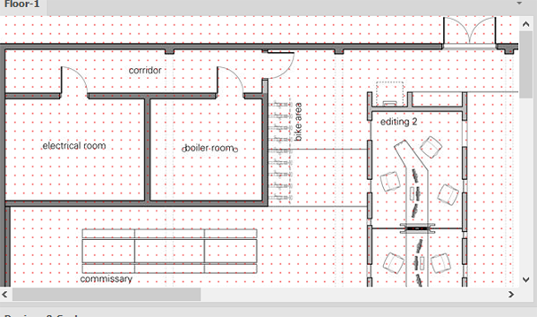
Selecting a grid color will superimpose a grid onto the floor plan:
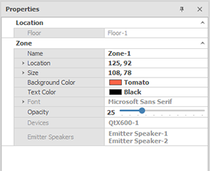
The Zone properties tab allows editing the name, type of zone, the physical size of the zone, as well user interface options (zone color and opacity.)
|
Field |
Properties |
|
Location - Floor |
Not user-editable; shows which floor the zone is located |
|
Name |
User editable |
|
Location |
Location allows modifying the X, Y axis of the zone location overlaying the floor plan |
|
Size |
Sets the dimensions (height and width) of the zone in relation to the floor plan |
|
Colors |
Sets the color of the zone overlay (Background Color) and label text (Text Color) |
|
Font |
Expand the Font category and select the font name, size, and properties |
|
Opacity |
Sets the opacity of the zone overlay |
|
Devices |
Not user-editable; shows which device is associated with the zone (must be connected to a speaker or emitter in the selected zone) |
|
Emitter Speakers |
Not user-editable; shows the number and name of emitters and speakers in the selected zone |
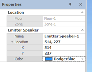
The Emitter & Speaker properties allows changing the selected emitter name, location, and color on the layout. Floor and Zone must be modified from their respective Properties windows.
|
Field |
Properties |
|
Location - Floor |
Not user-editable; shows which floor the emitter/speaker is located |
|
Location - Zone |
Not user-editable; shows which zone the emitter/speaker is located |
|
Name |
User-editable |
|
Location |
Location allows modifying the X, Y axis of the emitter location in the floor plan |
|
Colors |
Sets the color of the emitter speaker icon |
Device properties allow changing the selected device's name, location, and color as well as allowing assignment to a physical device discovered on the network. There are some differences between device types. NPX paging stations have different options than Qt X Controllers. When a device is added, the default name will be the device (QtX-# or NPX-#) with the number increasing with each device added. (ex. QtX-1, QtX-2, QtX-3, NPX-1, NPX-2....). Those default names may be changed.
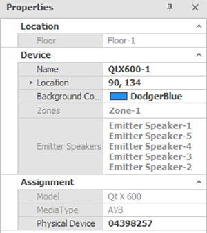
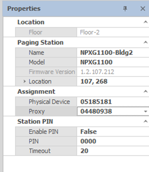
NOTE: Devices that are placed on a floor plan will be grey until they are assigned to a physical device. See example below:

Qt X Device Properties
|
Field |
Description |
|
Location - Floor |
Not user-editable; shows on which floor the device is located |
|
Name |
User-editable (take care that the device type is still identifiable if renaming) |
|
Location |
Location allows modifying the X, Y axis of the device location in the floor plan |
|
Background Color |
Sets the color of the Qt X device icon in the layout (when a physical device is assigned) |
|
Zones |
Not user-editable; shows which zones are associated with the device based on connected emitters/speakers in said zones |
|
Emitter Speakers |
Not user-editable; shows all emitters/speakers connected to the device in the layout |
|
Model |
Not user-editable; gives the model type of the device selected |
|
Media Type |
Populated based on the physical device selected |
|
Physical Device |
A list of physical devices will be shown if available based on the device selected in the layout. |
NPX Device Properties
|
Field |
Properties |
|
Location - Floor |
Not user-editable; shows which floor the device is located |
|
Name |
User-editable (take care that the device type is still identifiable if renaming) |
|
Model |
Allows change to the other microphone type (Gooseneck -G or Handheld -H) but keeps the same 4- or 10-button configuration (1040 or 1100) |
|
Firmware Version |
Not user-editable; shows current version if there is a physical device assigned |
|
Location |
Location allows modifying the X, Y axis of the device location in the floor plan |
|
Physical Device |
A list of physical devices will be shown - the selected NPX device must be associated with a discovered NPX device. |
|
Proxy |
The dropdown menu shows list of Qt X controllers on the same floor layout. Each NPX device must be associated with a controller (max of 4 per controller). |
|
Enable Pin |
True / False choice - If True, the pin number must be entered on the NPX device to initiate a page. |
|
Pin |
4-digit number that must be entered if the Pin Lock is enabled |
|
Timeout |
Sets the time (seconds) that the NPX device is unlocked for a page initiation if the Pin Lock is engaged. Default value is 20 seconds. |
Physical devices available on the network that match the device type selected in the layout will be shown in the Physical Device drop-down. Once selected, the Media Type will automatically populate. The Media type follows the Qt X system value and is not editable.
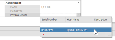

See Devices and Device Settings for more information on assigning devices to a system ,etc.
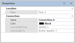
Connectors are representative of the physical cabling that connects emitters and speakers to one another and to the sound masking device. Users may change the color or naming.
|
Field |
Properties |
|
Location - Floor |
Not user-editable; shows which floor the connector is located |
|
Name |
User-editable |
|
Color |
Sets the color of the connector |
|
Connected From |
Not user-editable; shows the device or emitter/speaker where the connector begins |
|
Connected To |
Not user-editable; shows the emitter/speaker where the connector terminates |