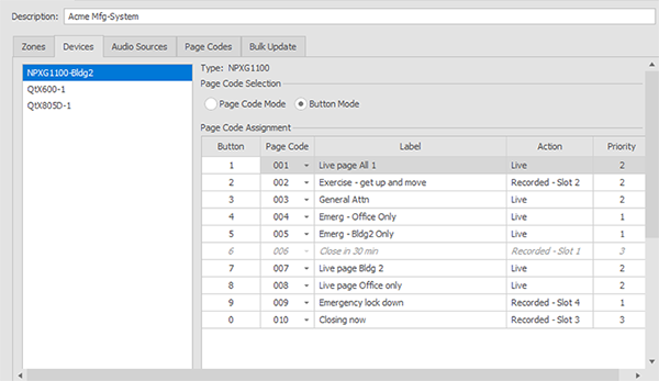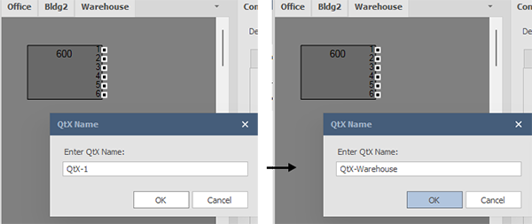
Any Qt X devices that have been placed on the layout will be shown in the Devices tab window. Device names, by default, depend on the device (Qt X or NPX) and would be named numerically in the order they were created (QtX-1, QtX-2, QtX-3, etc.). Device names may be changed as you are adding them, or from the device's Properties window.

When a Qt X device is selected, its Logic, Input and Output settings will be shown in the field to the right. Devices will have different output options available depending on the type of device selected. Logic functions are the same, regardless of the Qt X device selected.
The Logic functions consist of configurable GPIO inputs/outputs (2), a Push to Talk input and two Privacy outputs. Each of the GPIO options contain different settings, including priority, zone selection, specific to the option chosen.
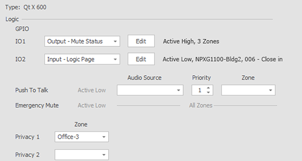
Specific port functions are detailed below. Click here for a detailed overview of logic ports, including pin-outs, use-cases, etc.
Custom GPIO Ports provide 5 options for each port from a dropdown list
Input options: Mute, Push To Talk, and Logic Page
Output options: Mute Status and Talk Now
Select the coverage zones
"Active Low" selection is available for all options
The dedicated Push to Talk is a function to allow for analog paging (not an NPX station) and is set as an input (not editable).
Users may select the audio source from the drop down (assigned in the Audio Source tab). Only sources that elect "page" in the Intents box are available.
Priority may be changed and a single or multiple zones may be selected.
Emergency Mute automatically overrides all audio in the the system and is not editable. This logic function would be connected to a fire alarm system.
NOTE: When a Qt X system comprised of multiple controllers is configured and connected via a network connection, only one physical "emergency mute" connection to a single controller location is required. A single contact trigger will propagate to all controllers included in the system.
Privacy 1 & 2 (light panels that indicate the status of sound masking,) do not have any audio functions or priority (nothing will override the Privacy Light function.) Privacy Lights may only be set to activate or not. The following parameters dictate when the privacy lights will activate in the selected zone:
Sound Masking must be enabled
Sound Masking is not set to mute
Sound Masking is set to higher than -20dB
The input controls allow selecting phantom power for an appropriately powered paging station/microphone as well as gain levels.
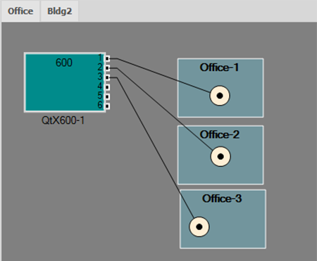
The number of outputs and emitter or speaker types shown is reflective of the device selected. Zones listed are indicative of the connections made on the actual floor plan layout. For example, in the image below, three zones are present on the floor where the device has been placed, emitters have been placed and connections made in the zones listed. If an output on a device is not connected to an emitter, the speaker/emitter selection will still be listed for that output but no zone will be listed.
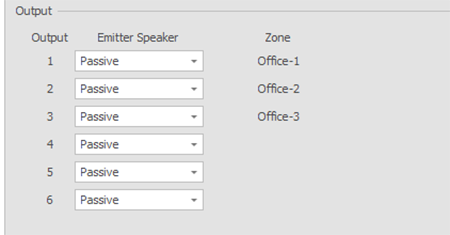
Outputs: the number of outputs per device:
|
Device |
Number of Zone Outputs |
|
Qt X 300/300D |
3 |
|
Qt X 600/600D |
6 |
|
Qt X 800/800D |
8 |
|
Qt X 805/805D |
8 |
Emitter/Speaker types available are indicative of the device selected. The Qt X 805/805D also has mirrored line level outputs for longer runs using 70V/100V speakers and an amplifier.
|
Device |
Speaker/Emitter Types |
|
Qt X 300/300D |
Passive/Active |
|
Qt X 600/600D |
Passive/Active |
|
Qt X 800/800D |
4/8 Ohm or DS1320 |
|
Qt X 805/805D |
4/8 Ohm or DS1320 |
Users should select the speaker-type based on what is physically installed in the system:
IMPORTANT NOTE: When active emitters are installed in a system, 'Active' must be selected in the Output window. The speaker/emitter type is not assignable from the controller front panel. Passive emitters are the default output type, and active emitters employ a different sound masking spectrum. If the emitter type isn't changed to Active, the installer may not be able to properly adjust the output levels for proper masking performance, and the active emitters in that zone may be damaged by the higher passive output.
IMPORTANT NOTE: when a DS1320 is selected, a predetermined/proper sound masking spectrum is configured.
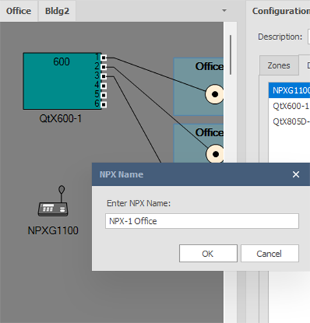
Any NPX devices that have been placed in the layout will be shown in the Devices panel. Device names, by default, are named numerically in the order they are created (NPX-1, NPX-2, etc.). Device names can be changed as they are added to the layout (pop-up window) or from their Properties window once placed.
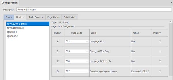
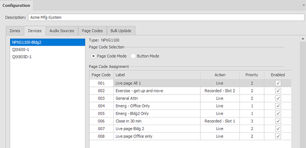
When an NPX is selected, the Page Code Assignment panel is displayed. Page codes must be assigned to a button (NPXG1040, NPXH1040) or enabled (NPXG1100, NPXH1100) to be available once configured. The 10-button NPX devices also have a Button Mode option where particular pages can be assigned to a numbered button allowing for a single button press to initiate an assigned page. Go to Page Codes for more information.
NOTE (10-button models): If Button Mode is engaged, only 10 page codes assigned to buttons will be available to that station. When Button Mode is chosen, by default, the first 10 page codes assigned to that station will be assigned in numerical order, but the list and order can then be modified (see below).
NPXG1040, NPXH1040 (4-button) page code assignment.
NPXG1100, NPXH1100 (10-button) - Page Code Mode.
NPXG1100, NPXH1100 (10-button) - Button Mode with available page code list showing.
